HF Noise monitoring system running from Live Ubuntu USB flash drive.
Ubuntu Live Noise Monitoring system with Persistence. 16Gb
I wanted a Preconfigured RF Noise monitoring system that I can run on my Laptop when ever I am not using it for something else.
I made this Ubuntu 16.04 Live memory stick .
So how dose it work?
Configure your BIOS to boot from USB flash drive and you should then see the following screens.
Just pres enter to continue
If you see the error above just pres Enter You should then get a screen where you can select how you want to boot your environment Persistent or not.
Select the Persistent live boot.
Select the Persistent live option.
You could then see a screen for a few seconds looking like this.
Black screen before startup
This picture is of Ubunto 17.10 The Noise system is on Ubuntu 16.04
Here is some of the sunscreens of some of the functionality
Generally a balun consists of two wires (primary and secondary) and a toroid core: it converts the electrical energy of the primary wire into a magnetic field. Depending on how the secondary wire is done, the magnetic field is converted back to an electric field..
Balun
A Balun is a device that joins a balanced line (one that has two conductors, with equal currents in opposite directions, such as a twisted pair cable) to an unbalanced line (one that has just one conductor and a ground, such as a coaxial cable). A balun is a type of transformer: it's used to convert an unbalanced signal to a balanced one or vice versa. Baluns isolate a transmission line and provide a balanced output.
In a Balun, one pair of terminals is balanced, that is, the currents are equal in magnitude and opposite in phase. The other pair of terminals is unbalanced; one side is connected to electrical ground and the other carries the signal.
The Baluns (transformer tipe) also translate impediment differences. (450Ohm to 50m )
Some impedance matching guide lined.
A (1 to 1) BALUN is mostly used with center taped Dipoles. (50 Ohm Antenna to 50 Ohm Coaxial cable)
A (2 to 1) BALUN is mostly used with HF quads and loop Antennas (100 Ohm Antenna to 50 Ohm Coaxial cable)
A (4 to 1) BALUN is mostly used with Off center dipoles, Windom and Sky wire loops 80m and 160m band (200 Ohm Antenna to 50 Ohm Coaxial cable)
A (6 to 1) BALUN is mostly used with Off center dipoles that is installed higher than about 25m. (300 Ohm Antenna to 50 Ohm Coaxial cable) you could also use 300 ohm robin cable and the mach it to 50 ohm.
A (9 to 1) BALUN is mostly used with end fed long wire antennas. (450 Ohm Antenna to 50 Ohm Coaxial cable) you could also use 450 ohm ladder line and the mach it to 50 ohm.
50 Ohm coaxial cable vs 450 Ohm or 600 Ohm ladder or window line?
Coaxial cable 50,75 or 92Ohm
Ladder feed line
The primary advantages of coax with respect to ladder line are
Most transceivers are equipped with 50 ohm coax connectors, whereas using ladder line requires a Balun or balanced tuner
Coax cable is not affected by nearby metal objects, unlike ladder line
The impedance of coax doesn't change when it rains or snows, unlike ladder line
The primary advantages of ladder line with respect to coax are
Lower loss at frequencies of 28 MHz and up words
Easier to make connections
Can drive a balanced antenna (e.g. a dipole) without a Balun
Building my Eggbeater II Omni low Earth orbit satellite Antennas for 70cm and 2M.
70cm Egg Beater
I only had vertical 5/8 ground plane antenna fro 70cm and 2m band and wanted to get better reception on the new cube satellites frequency.
This assembly is based on the Jerry, K5OE Eggbeater II design.
More details at http://wb5rmg.somenet.net/k5oe/Eggbeater_2.html
70cm Eggbeater II
First get the following items:
1) 2.5 mm SQ (Minimum) Flex cable used in normal 15A plug cable with solid copper core. (about 2m)
2) 50mm PVC Plumbing pipe.(3m lent)
3) 50mm PVC end caps (qty 1)
4) RG65 Coax Cable for matching unit (18.5 cm) 93 Ohm
5) 3mm x 15mm screw with nuts (qty 4)
6) Spade terminals (qty 8)
7) RG58 or recommended RG213 coaxial cable feed line 50 Ohm. 2m Eggbeater II The 2 meter loops are 51 cm wide by 63 cm tall; 2 meter the reflectors are 100.5 cm long and 101 cm below the driven elements. 137 MHz WX Sat Dimensions The loops should be built with # 8 AWG wire and the reflectors should be increased to about 1/4" diameter. The loops will be 54 cm wide by 66.5 cm high. The reflectors will be 107 cm long and 108 cm distance from the feed point. The RG-62 will be 45 cm long (plus 2.5 cm at each end).
Phasing line The 70 cm phasing line is (13.5 cm) long and the 2 meter phasing line is (41.5 cm) long. Cut the RG-62 about (5 cm) longer than these measurements and leave (2.5 cm) at each end to strip the insulation, peel back the braid, strip the center conductor, and attached the ring lugs.
The 70 cm loops are (17 cm) wide by (21 cm) high and the reflectors is (33.5 cm) long and (33 cm) below the driven elements
Step by step instructions to assemble 70cm Antenna.
1) Strip the cable from the plastic flex cable.
2) Drill the 50mm PVC end caps with 3mm drill diagonal from each other and mount the wire crimp lugs with the screws and nut.
Crimp lugs
50mm PVC end cap assembled.
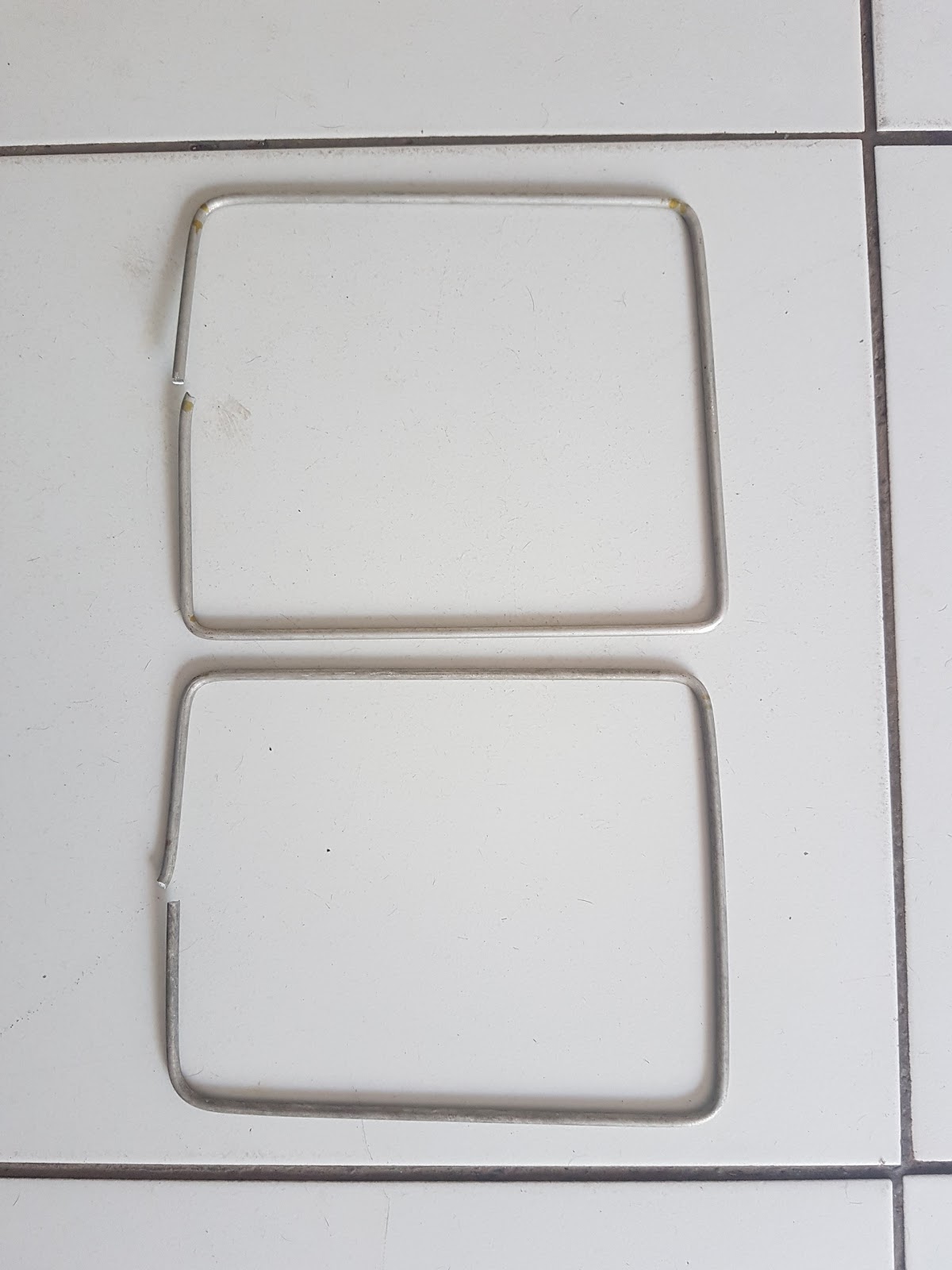
2) Bend the wire 21 x 17cm
21cm high
17cm wide
3) Cut the wire end to still give you 17cm with when inserted on external crimp lugs and crimp the lugs with long nose players or crimping tool. (use insulation to hold top section together.)
Assembled active loops
4) Cut two lengths of cable of 33.7 cm and straiten.
5) Cut about 5mm wide and 1cm deep square cuts out of 50mm PVC end as on picture below.
Cut out squares from pipe end.
6) Then mount the assembled end cap with active elements on to PVC pipe where you have cut out the squares.
Assembled end cap on PVC pipe
5)Then drill 4 holes 33cm below the driving elements diagonal in pipe
I have drilled 4 hole above and 4 holes below the 33cm distance so I can fine tune the SWR
Drilled 12 holes 33cm below driver elements
6) Assemble the previously cut 33.7cm wires in the center drilled holes as in picture below.
7) Assembly of feed line next weakened.
Cut the RG-62 about (5 cm) longer than these measurements and leave (2.5 cm) at each end to strip the insulation. The 70 cm phasing line is (13.5 cm) long.(add 5 cm to strip 2.5cm on ether side)
Here is some pictures of the construction of 2m Eggbeater
2m Feedline
RG65 and RG58 feadline (2m)
2m Top support
Assembly of top section (2M)
2m Feed line connection
Adding phase and feed line (2M)
2m and 70cm Eggbeater Antenna
Add caption
Some more pictures from Hams
70cm Eggbeater Jan 2014
Here is some more pictures from hams who have build the Eggbeater.
70cm Eggbeater Jan 2014
2m Eggbeater Jan 2014
2m Eggbeater Jan 2014
2m Eggbeater and 30m dipole
My new 2m Egg beater
I had some problems with Big OWL bending my 70cm Eggbeater antenna several times where after I decided to redo the 70cm Eggbeater with bigger 5mm Aluminum Rods.
Bend by Large Owl
Owl
Here is a picture of my refurbish 70cm Eggbeater.
I had to bend the Aluminum with a gas torches heating up the corner when bending it as it broke if I tried to bend it if it was room temperature .