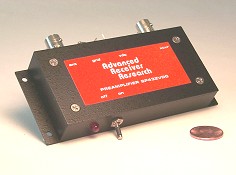
I want to modify the Ellies Dual Port LNB so that the output frequency would be ether on 70cm 435Mhz or 2M 145Mhz so that it can be used on the QO-100 Satellite directly to VHF/UHF SSB rigs.
Here is an opened LNB.
Opend LNB
Here you can see the two local filters to the two ports.
The Main Mixer and PLL LO seem to be Rafael Micro RT320n
Top View
The Mixer and LO and PLL seem to be Rafael Micro RT320n
Rafael Micro RT320n
It seem Like the Local Crystal is 25Mhz
Crystal is 25Mhz
What this mean if I change the LO Crystal frequency I should be able to force the IF to the required Output to ether on 70cm 435Mhz or 2M 145Mhz
I have created a Spreadsheet to calculate the required IF frequencies so you can listen to QO-100 on the required Ham band.
I did some calculations and the LO to Crystal frequency = LO / 390
see calculated values
Blue / Red is crystal frequency for your LO in LNB
How do you build a 1U Cube-Sat Linear transponder using SDR / DSP technology with limited Power?
Requirements:
Satellite requirements.
Linear Transponder 70cm (437Mhz) up-link and S band (2.4GHz or 1.2Ghz down) Down-link (Bandwidth ? 250Khz on 70cm ?)
Satellite Low Earth orbit (LEO) altitude between 650 kilometers. We need this so we can calculate path loss and RF power and antenna gain requirements.
Available Power 1.5W for transponder from Solar panels and battery system.
Telemetry mode? CW / AX25 / AFSK 9k6 /....
UHF Beacon recomendation.
UHF Beacon interval: about 55 seconds
UHF Transmit power: ~ 1 W
AFSK AX25 1k2 and fallback of CW 10WP
Satellite antennas for 70cm ? and (Polarization ?)
Satellite antennas for 2.4Ghz / 1.2Ghz and (Polarization ?)
Telemetry Requirements ? (ID, Temperature, Power in, Power out, Battery left, Transponder Mode status, Antenna Status, Satellite Orientation, ........)
Inter board Connector Specification (PC/104 communication)
OBC, SOLAR,charger,Orientation and Battery from existing Satellite ?
1 U Cube-Sat Space frame from existing Satellite (10x10x10) 1kg
DSP 10 to 14Bit A/D /D/A Dynamic range. what is good enough ?
PCB Board size details PC104 with cutouts for wire.
Space frame and Solar panel frame and Antenna deployment. (out of scope)
Solar panels. (Out of Scope)
Power regulator and Charge regulator and Battery. (out of Scope)
Orientation controls. (out of scope) (Stabilization)
RF Linear Transponder using SDR / DSP. (70cm up 2.4Ghz or 1.2Ghz down)
OBC (In scope ARM M4 or possibly A9) (FreeRTOS)
Inter board communication standard.
Out of Scope for now:
Space frame, Solar panels and panels frame.
Solar panels
Power regulator and Charge regulator and Battery.
Orientation controls.
In scope for now:
Linear Transponder using SDR / DSP. (ARM Processor possibly not FPLG due to power constraint.)
Building my Eggbeater II Omni low Earth orbit satellite Antennas for 70cm and 2M.
70cm Egg Beater
I only had vertical 5/8 ground plane antenna fro 70cm and 2m band and wanted to get better reception on the new cube satellites frequency.
This assembly is based on the Jerry, K5OE Eggbeater II design.
More details at http://wb5rmg.somenet.net/k5oe/Eggbeater_2.html
70cm Eggbeater II
First get the following items:
1) 2.5 mm SQ (Minimum) Flex cable used in normal 15A plug cable with solid copper core. (about 2m)
2) 50mm PVC Plumbing pipe.(3m lent)
3) 50mm PVC end caps (qty 1)
4) RG65 Coax Cable for matching unit (18.5 cm) 93 Ohm
5) 3mm x 15mm screw with nuts (qty 4)
6) Spade terminals (qty 8)
7) RG58 or recommended RG213 coaxial cable feed line 50 Ohm. 2m Eggbeater II The 2 meter loops are 51 cm wide by 63 cm tall; 2 meter the reflectors are 100.5 cm long and 101 cm below the driven elements. 137 MHz WX Sat Dimensions The loops should be built with # 8 AWG wire and the reflectors should be increased to about 1/4" diameter. The loops will be 54 cm wide by 66.5 cm high. The reflectors will be 107 cm long and 108 cm distance from the feed point. The RG-62 will be 45 cm long (plus 2.5 cm at each end).
Phasing line The 70 cm phasing line is (13.5 cm) long and the 2 meter phasing line is (41.5 cm) long. Cut the RG-62 about (5 cm) longer than these measurements and leave (2.5 cm) at each end to strip the insulation, peel back the braid, strip the center conductor, and attached the ring lugs.
The 70 cm loops are (17 cm) wide by (21 cm) high and the reflectors is (33.5 cm) long and (33 cm) below the driven elements
Step by step instructions to assemble 70cm Antenna.
1) Strip the cable from the plastic flex cable.
2) Drill the 50mm PVC end caps with 3mm drill diagonal from each other and mount the wire crimp lugs with the screws and nut.
Crimp lugs
50mm PVC end cap assembled.
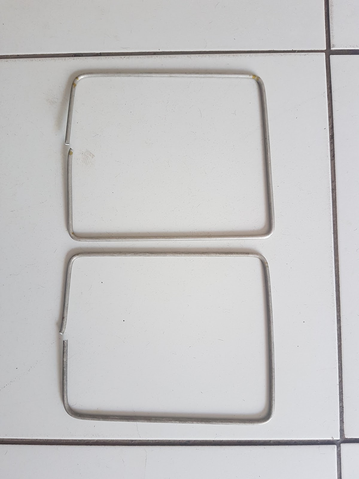
2) Bend the wire 21 x 17cm
21cm high
17cm wide
3) Cut the wire end to still give you 17cm with when inserted on external crimp lugs and crimp the lugs with long nose players or crimping tool. (use insulation to hold top section together.)
Assembled active loops
4) Cut two lengths of cable of 33.7 cm and straiten.
5) Cut about 5mm wide and 1cm deep square cuts out of 50mm PVC end as on picture below.
Cut out squares from pipe end.
6) Then mount the assembled end cap with active elements on to PVC pipe where you have cut out the squares.
Assembled end cap on PVC pipe
5)Then drill 4 holes 33cm below the driving elements diagonal in pipe
I have drilled 4 hole above and 4 holes below the 33cm distance so I can fine tune the SWR
Drilled 12 holes 33cm below driver elements
6) Assemble the previously cut 33.7cm wires in the center drilled holes as in picture below.
7) Assembly of feed line next weakened.
Cut the RG-62 about (5 cm) longer than these measurements and leave (2.5 cm) at each end to strip the insulation. The 70 cm phasing line is (13.5 cm) long.(add 5 cm to strip 2.5cm on ether side)
Here is some pictures of the construction of 2m Eggbeater
2m Feedline
RG65 and RG58 feadline (2m)
2m Top support
Assembly of top section (2M)
2m Feed line connection
Adding phase and feed line (2M)
2m and 70cm Eggbeater Antenna
Add caption
Some more pictures from Hams
70cm Eggbeater Jan 2014
Here is some more pictures from hams who have build the Eggbeater.
70cm Eggbeater Jan 2014
2m Eggbeater Jan 2014
2m Eggbeater Jan 2014
2m Eggbeater and 30m dipole
My new 2m Egg beater
I had some problems with Big OWL bending my 70cm Eggbeater antenna several times where after I decided to redo the 70cm Eggbeater with bigger 5mm Aluminum Rods.
Bend by Large Owl
Owl
Here is a picture of my refurbish 70cm Eggbeater.
I had to bend the Aluminum with a gas torches heating up the corner when bending it as it broke if I tried to bend it if it was room temperature .