Showing posts with label Band Pass Filter. Show all posts

Wednesday, September 7, 2022

2.4GHZ uplink to 10Ghz downlink Satellite

 2.4Ghz to 10Ghz Satellite transponder

I am thinking of building a  2.4Ghz up link to 10Ghz Down link  Satellite Transponder 


10Ghz Up-link and 2.4Ghz down link or the 2.4Ggz up link and 10Ghz down

Up-link 2.4 to 10Ghz can reasonably easy be done with SDR (pluto using first harmonic on output for 10Ghz)

I wanted to do it with SDR and was looking for reasonably priced Full duplex TX/RX SDR and was looking at the Pluto Plus SDR

see details here for using Python to controller the Pluto

https://pysdr.org/content/pluto.html

Looking at the Band Plan at 2.4Ghz


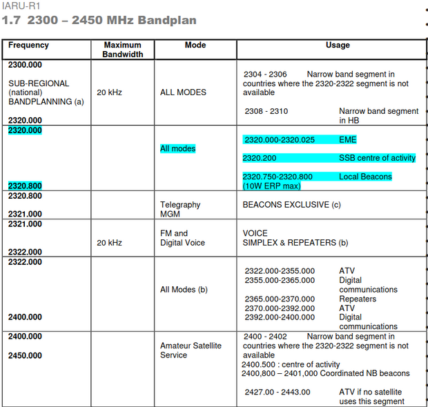
It seems we have about it seems we can use the band from about 2320Mhz up to 2400Mhz

 10Ghz Band Plan


 and on the 10Ghz Band 10Ghz up to 10.500Ghz

So 2.4Ghz uplink and 10Ghz downlink could easily be done with pluto plus and raspberry pi 3 using Gnuradio using the first harmonic on 5Ghz


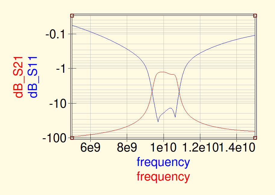
10Ghz Micro strip Band pass filter

installing qusc-rflayout

cd

git clone https://github.com/thomaslepoix/Qucs-RFlayout.git
cd Qucs-RFlayout/
ls
mkdir build
cd build
cmake ../
make
sudo make install

see if it works by running it

qucsrflayout

 Create the netlist using the following command (input file output file)

sudo qucs -n -i "/usr/share/qucs/examples/microstrip.sch" -o "/usr/share/qucs/examples/microstrip.net"


Ground station equipment same as QO-100

Creating pcb

Using the Qusc-RFlayout utility to create the pcb from design 

select your sch file and click read

Then select the output folder at the bottom and select write to create the kicad pcb file


Open the kicad_pcb file in kicad


Here is the curve simulated on Qucs


Band pass section


Installing qucs from this url https://github.com/thomaslepoix/Qucs-RFlayout


1) Qty 10 of the Mini Circuits SXBP-150+  filter
2) Qty 2 of the Mini Circuits ZX60-06183LN+ amp

Here is the circuit diagram of my 10 Ghz RF amp design


Simulating the rf Stub  (3.9mm 90deg)


1/4 wave stub at 10ghz


Ref :using micro strip calculator Qucs


Monday, May 21, 2018

How to Create a Linear Transponder using a RTL Dongle and HackRF with Gnu Radio.

How to Create a Linear Transponder using a RTL Dongle and HackRF with Gnu Radio.

I wanted to test the concept of a linear Transponder and how difficult would it be to build it with conventional components.
Hardware Configuration
Hardware required to build the Transponder.
  1. SDR IQ demodulator with rtl dongle (RF In)
  2. SDR IQ DSP processing system. Gnu Radio (DSP processing)
  3. SDR IQ Modulator. HackRF (RF Out)
  4. Background management system. (OBC) for additional telemetry.
Software required for Transponder.
  1. SDR IQ demodulator. rtl dongle (RF In)
  2. SDR IQ DSP processing system. Gnu Radio (DSP processing)
  3. SDR IQ Modulator. HackRF (RF Out)
  4. Background management system. (OBC)

Video of working Transponder.


Gnu Radio.


Transponder Block Diagram

RTL SDR Block.

RTL-SDR Source

Low Pass Filter Block.

 
Low Pass Filter Block

AGC Block.

AGC Block

Power Squelch.

Power Squelch

Osmocom Sink. (HackRF)

Osmocom Sink (HackRF)

FFT. (Spectrum View of input)

FFT Spectrum View

REF: Power point Slides at AMSAT SA

Ref:Source code is available on Github Version 4

Wednesday, October 19, 2016

VHF 2m Low pass filter design for 146Mhz ideal for Raspberry Pi

VHF 2m Low pass filter design for 146 Mhz ideal for Raspberry Pi 

I wanted to use the Raspberry Pi SDR TX capabilities using the IO pins to generate RF.
The following was possible.
APRS
FM and SSB and CV
WSPR
SSTV....

There is a very nice library that will run on Raspberry Pi one B called rpitx witch can generate CW,SSB,FM SSTV...

The problem in using a Digital IO pin on the pi to generate RF signal would mean it will generate a squire wave signal witch has lots of harmonics. To solve the harmonic problem you will need to build a low pass filter.
Harmonic about 25 db down with now filter.


This harmonic would not be in regulation with rf transmission and would therefore need to create a low pass filter to remove the harmonics.

Here is a filter I build to get rid of the harmonics.

RFSim99 application.


Here is the Low pass filter spectrum analyzer curve on my LWT500,
The Harmonic level should be about 25 db below the carrier.

LPF Curve for 146Mhz (1 Harmonic down about 25db)


Here is some photos of the veroboard test filter I am now busy make a PCB for Raspberry Pi with a small 10db amp.


146 Mhz Low pass filter SMD components

Still need to replace the two wires with Coaxial cable.
This filter board with 7 stage low pass filter will be available soon. (60db)
3D model of 2m Filter board
I will still add a screenshot with the Filter attached later.
Boards has arrived. Assembly and testing will start.