|
| Bacar Balloon |
I wanted to take part in a local BACAR Balloon experiment and wanted to send my GPS position via the APRS network and also send a CW beacon every 7 minutes. I got an opportunity to add my payload to a school project.
 |
| Raspberry TX Hat for 2m Band |
So I decided to use the the 2m transmitting board form Giga technology plug it on the raspberry pi. this should give me about 32.7mW (15.1dBm)
Power is a bit low but its a good for now.
 |
| Balloon Telemetry System |
BACAR launch details is available here.
http://secundaweather.co.za/blog/?p=2012
Learnings
- Power to Low (Working on model 2 with a power output of 100 to 900mw output.
- Need to record everything that hapens in Local log so you can recover more information that you would send with Telemetry.
- Raspberry Pi 3
- Giga Technology TX PI HAT for 2M
- RTL dongle for RX
- Giga Technology USB GPS unit.
- Giga Technology Battery and Powersupply Boards.
- Temperature sensor
- Optional USB Camera for CCTV.
 |
| High Level Hardware configuration |
Software.
- CW (CW tone generation for Beacon transmission)
- Direwolf. (AX 25 telemetry generation for Temperature and on-board sensors board 1200 AFSK)
- rtl_sdr (SDR receiver software for incoming commands controlling transponder)
- rpitx (RF transmitter details)
- ALSA loopback (this is needed to send audio between direwolf cw and rpitx)
- gpsd GPS positioning server read by direwolf APRS transmission
- Kal (rtl dongle frequensy calibaration details)
- csdr DSP libraries that can be used for SDR.
- Some shell scripts taing this all together. Download from github https://github.com/antonjan/Raspberry_Telemetry
 |
| Software Block Diagram |
Lets install the software for the system.
sudo apt-get install cw
sudo apt-get install direwolf
sudo apt-get install rtl-sdr
sudo apt-get install gpsd
sudo apt-get install alsa-utils
sudo modprobe snd-aloop
sudo apt-get instal python
Install the csdir sdr libraries doing the following.
git clone https://github.com/simonyiszk/csdr
cd csdr
make
sudo make install
Get the direwolf example configurations
git clone https://github.com/wb2osz/direwolf
Lets install aprs utility.
got home directory
cd
git clone https://github.com/casebeer/afsk.git
cd afsk
sudo pip install afsk
sudo pip install --allow-external PyAudio --allow-unverified PyAudio PyAudio
Lets test aprs util
aprs
You should see the following
usage: aprs [-h] -c CALLSIGN [--destination DESTINATION] [-d DIGIPEATERS]
[-o OUTPUT] [-v]
INFO
aprs: error: too few arguments
Lets check if alsa loop installed
sudo arecord -l
you should see this
card 2: Loopback [Loopback], device 0: Loopback PCM [Loopback PCM]
Subdevices: 8/8
Subdevice #0: subdevice #0
Subdevice #1: subdevice #1
Subdevice #2: subdevice #2
Subdevice #3: subdevice #3
Subdevice #4: subdevice #4
Subdevice #5: subdevice #5
Subdevice #6: subdevice #6
Subdevice #7: subdevice #7
card 2: Loopback [Loopback], device 1: Loopback PCM [Loopback PCM]
Subdevices: 8/8
Subdevice #0: subdevice #0
Subdevice #1: subdevice #1
Subdevice #2: subdevice #2
Subdevice #3: subdevice #3
Subdevice #4: subdevice #4
Subdevice #5: subdevice #5
Subdevice #6: subdevice #6
Subdevice #7: subdevice #7
You cal also check it in the sound volume control
Right click on the Sound icon and select setting and you should see the following
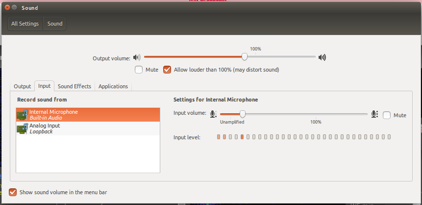 |
| Input Tab should have the loopback sound card |
 |
| Output Sound Card should have loopback |
Lets test CW
cw -h
You should see the help
Lets test gpsd
gpsd -h
You should see the gpsd help
Install the gps on USB port.
We now need to find out what is the usb port for your GPS device so we can run the following command. sudo gpsd -D 5 -N -n /dev/ttyACM0
We assume here that your usb device is /dev/ttyACM0
Run this command and then plug in and out your gps on usb port.
tail -f /var/log/syslog | grep ttyAC
You will the see something like this.
/dev/ttyACM0
Then run the command sudo gpsd -D 5 -N -n /dev/ttyACM0 replacing it with your GPS usb port.
gpsd:PROG: Changed mask: {ONLINE|TIME|LATLON|ALTITUDE|STATUS|MODE|PACKET|PPSTIME} with reliable cycle detection
gpsd:PROG: GPGSA sets mode 3
gpsd:CLIENT: => client(0): $GPGSA,A,3,08,27,16,09,,,,,,,,,4.12,1.97,3.61*0D\x0d\x0a
gpsd:PROG: Changed mask: {ONLINE|MODE|DOP|PACKET|USED} with reliable cycle detection
gpsd:PROG: Partial satellite data (1 of 4).
gpsd:CLIENT: => client(0): $GPGSV,4,1,14,01,64,012,08,03,05,014,,04,06,121,,07,69,274,18*72\x0d\x0a
gpsd:PROG: Partial satellite data (2 of 4).
gpsd:CLIENT: => client(0): $GPGSV,4,2,14,08,43,151,28,09,11,321,22,11,88,165,17,16,15,081,21*7E\x0d\x0a
gpsd:PROG: Partial satellite data (3 of 4).
gpsd:CLIENT: => client(0): $GPGSV,4,3,14,17,06,290,22,22,14,033,16,23,04,348,,27,14,129,08*7A\x0d\x0a
gpsd:CLIENT: => client(0): $GPGSV,4,4,14,28,16,230,11,30,40,230,21*75\x0d\x0a
gpsd:PROG: Changed mask: {ONLINE|DOP|SATELLITE|PACKET} with reliable cycle detection
There is also another utility that could give you the status of the gpsd service.
Ok lets make our gpsd configuration permanent.
Edit the following configuration file using your favorite text editor.
and change the usb interface to what was detected above
sudo Vi /etc/default/gpsd
# /etc/default/gpsd
START_DAEMON="true"
GPSD_OPTIONS="-n"
DEVICES="/dev/ttyAMA0"
USBAUTO="false"
GPSD_SOCKET="/var/run/gpsd.sock"
Lets restart the gpsd service
sudo systemctl stop gpsd.socket
sudo systemctl start gpsd.socket
You can now test if it works fine with the following command
sudo gpsmon
You should see the following if all is ok with gps connected.
 |
| This is the GPS details as read by GPSD |
Lets test direwolf
direwolf -h
You should see the direwolf help screen in white inverse.
Ok lets check rtl_sdr. (the SDR receiving software)
Plug-in your rtl dongle and then run the following command.
sudo rtl_test
You should see some test results and gain parameters supported by your device.
Ok
Connect your ds18b20 temperature sensor.
One of the coolest things about OneWire and DS18B20 temperature sensors is that each sensor has its own embedded address so you can have many of them on 1 data wire.

Configure the raspberry pi to read the temperature.
Edit the following config file
sudo vi /boot/config.txt
Add the following at the bottom of the file
dtoverlay=w1-gpio
Then reboot the pi
sudo reboot
We now need to load the device drivers for the temperature sensor.
sudo modprobe w1-gpio
sudo modprobe w1-therm
Now check if the device was loaded
ls /sys/bus/w1/devices
you should see a directory like this below
28-000007602ffa
Go into this directory replacing the part in yellow with your directory
cd /sys/bus/w1/devices/28-000007602ffa
Now run the following command to get the temperature.
w1_slaveYou should see something lie this.
bd 01 4b 46 7f ff 03 10 ff : crc=ff YES
bd 01 4b 46 7f ff 03 10 ff t=27812
We can now use a python script to read the readings
get the python code from github using the following command
git clone https://github.com/pimylifeup/temperature_sensor.git
goto the new directory that was created. temperature_sensor
cd temperature_sensor
Give the application executable writes by using the following command
chmod 776 temperature_sensor_code.py
Then run the command
./temperature_sensor_code.py
You should see the temperature readings scrawling on the screen.
Ok we can stop it with CTRL C.
Ok now all seems to be working for the temperature readings
We now need to test the Radio transmitter.
Please note you need to have a Amateur Radio license to do this as you will be transmitting on the Amateur allocated frequencies.
Install the Raspberry Pi hat on the Raspberry Pi and then test the transmitter with the following commands.
Clone the following examples in your home directory from github
git clone https://github.com/antonjan/Raspberry_Telemetry.git
cd to the Raspberry_Telemetry directory.
Connect a 2m external antenna to the raspberry Pi Hat SMA connector.
run the following command
sudo ./Start_Carier_check.sh
Now check for a rf carrier on the following frequency
U can use a SDR dongle or HT (Baofeng) or spectrum analyzer if you have one.
The frequency can be changed by editing this file and changing the yellow value
vi ./Start_Carier_check.sh
sudo rpitx -m VFO -f 145300 -c1
Now that we have the transmitter tested we can start testing the telemetry.
Lets start doing some real time applications.
Now lets configure the APRS and CW telemetry to send sensor data and call sign. I suggest using 70cm up-link and 2M down-link not to overdrive the receiver front end. ( There is a diplex available from Giga technology)
 |
| 2m and 70cm Diplexer |
- Sending APRS telemetry every minute with GPS and temperature readings.
- Sending a CW (morse code) with calsign and temperature reading every two minutes.
- Lets test a command to control the system. Replying with APRS got command.
- I wanted to send telemetry every minute but decided to make it a prime number just in case there is two telemetry transmissions disturbing each other so this would be helping to resolve this problem. (67 seconds)
Sending APRS telemetry every minute with GPS and temperature readings.
Download the following shell scripts
1) wget https://raw.githubusercontent.com/antonjan/Raspberry_Telemetry/master/sh/cron_aprs_gps_position.sh
2) wget https://raw.githubusercontent.com/antonjan/Raspberry_Telemetry/master/sh/crontab_bacar_cw.sh
3) wget https://raw.githubusercontent.com/antonjan/Raspberry_Telemetry/master/sh/crontab_bacar_aprs.sh
4) wget https://raw.githubusercontent.com/antonjan/Raspberry_Telemetry/master/telem-balloon_2.conf
Lets edit the file for your path.
vi cron_aprs_gps_position.sh
Fix the yellow with path to your direwolf file.
#load looback and start gpsd service for gps data.
sudo /usr/sbin/gpsd -D 5 -N -n /dev/ttyACM0 &
sleep 5
sudo /sbin/modprobe snd-aloop
sleep 2
#We now will write out the audio from loopback from direwolf to a wav file
sudo timeout 10s arecord -c1 -t wav -r 48000 --vumeter=mono -D hw:Loopback,1,0 -fS16_LE /home/pi/sh/direwalf.wav &
#We now will create a APRS audio withS position and send it to loopback device
sudo timeout 9s direwolf -c /home/pi/Downloads/direwolf/telemetry-toolkit/telem-balloon_2.conf
# we now wait for short wile
sleep 1
#we now convert the wav file in a format to transmit
sudo sox -v 0.3 -S /home/pi/sh/direwalf.wav /home/pi/sh/direwalf_sox.wav rate -L -s 48000
# we now wait for short wile
sleep 1
#we now convert the APRS audio file to a fm file for transmission.
sudo /home/pi/Downloads/rpitx_new/rpitx/pifm /home/pi/sh/direwalf_sox.wav /home/pi/sh/direwalf_sox.wav.ft
# we now wait for short wile
sleep 1
#We now transmit the the APRS gps postion on the frequensy 144,801Mhz
sudo /home/pi/Downloads/rpitx_new/rpitx/rpitx -i /home/pi/sh/direwalf_sox.wav.ft -m RF -f 144801 -c1Save the file
Lets send our first APRS GPS position.
Change the callsign in the telem-baloon_2.conf to your callsign
Check that the paths in the telem-baloon_2.conf and cron_aprs_gps_position.sh is correct in relation to the directory you check the code out.
run the script sudo ./cron_aprs_gps_position.sh and you should now send a gps position aprs message. If you change the frequency to your local packet (APRS in SA its 144.8Mhz)frequency you should see the Balloon Icon on the APRS server. https://aprs.fi/#!lat=60.169998&lng=24.94
You mite want to calibrate the TX frequency by changing the frequency in the script.
You can now add this script in a cron to send every 1minute ...
Here is an exsample just to send a message
sudo aprs --callsign NOCALL --output - "30mw Belloon Beacon de NOCALL" | csdr convert_i16_f | csdr gain_ff 7000 | csdr convert_f_samplerf 20833 | sudo rpitx -m RF -i - -f 144325 -c1
Ok lets now send some CW as a beacon.
Lets create a text file with the cw message we want to send.vi cw_text
enter the following example
32mw balloon experiment de NOCALSIGN
save the file (including the space in front)
we now will be using a different script crontab_bacar_cw.sh
edit this script.
vi crontab_bacar_cw.sh
#This script will send a cw at 10 words per minute
#Start GPS and alsa loopback
sudo /usr/sbin/gpsd -D 5 -N -n /dev/ttyACM0 &
sleep 5
sudo /sbin/modprobe snd-aloop
#now setup loopback to write to file
sudo /usr/bin/timeout 11s /usr/bin/arecord -c1 -t wav -r 48000 --vumeter=mono -D hw:Loopback,1,0 -fS16_LE /home/pi/sh/bacar_cw.wav &
# now send cw to loopback with cw_text.txt
sudo /usr/bin/timeout 10s /usr/bin/cw -s a -d hw:Loopback,1,0 -t 1000 -v 50 -f /home/pi/sh/cw_text.txt
sleep 1
#Now convert the file to format that can be converted to fm signal.
sudo /usr/bin/sox -v 0.9 -S /home/pi/sh/bacar_cw.wav /home/pi/sh/bacar_cw_sox.wav rate -L -s 48000
sleep 1
#now create transmission file for rpitx
sudo /home/pi/Downloads/rpitx_new/rpitx/pifm /home/pi/sh/bacar_cw_sox.wav /home/pi/sh/bacar_cw_sox.wav.ft
sleep 1
#now send your CW (morse code on 144.328 Mhz) Change frequency as requerd
sudo /home/pi/Downloads/rpitx_new/rpitx/rpitx -i /home/pi/sh/bacar_cw_sox.wav.ft -m RF -f 144328 -c1
Save the file and run and test.
sudo ./crontab_bacar_cw.sh
Now listen on the tx frequency and run the script and you should here the message "32mw balloon experiment de YOURCALLSIGN"